Enclosure quality is set by process integration, not by any single machine. This explainer walks the one-stop flow — drawing review, tolerance risk assessment, laser cutting on a TruMatic 6000, CNC punching on Amada, bending, MIG/TIG/spot welding, powder coating, FAI, and the QC photo pack — and shows what buyers should verify before releasing a first article.
Process Integration Explainer
Most enclosure problems a buyer sees at incoming inspection — a door that will not sit flat, a weld that pulls a panel out of square, a powder coat that chips at a folded corner — trace back to a decision made weeks earlier about how many vendors touched the part. Metal enclosure fabrication is a chain of processes, and every hand-off between cutting, bending, welding, and coating adds a tolerance stack and a place where accountability can disappear.
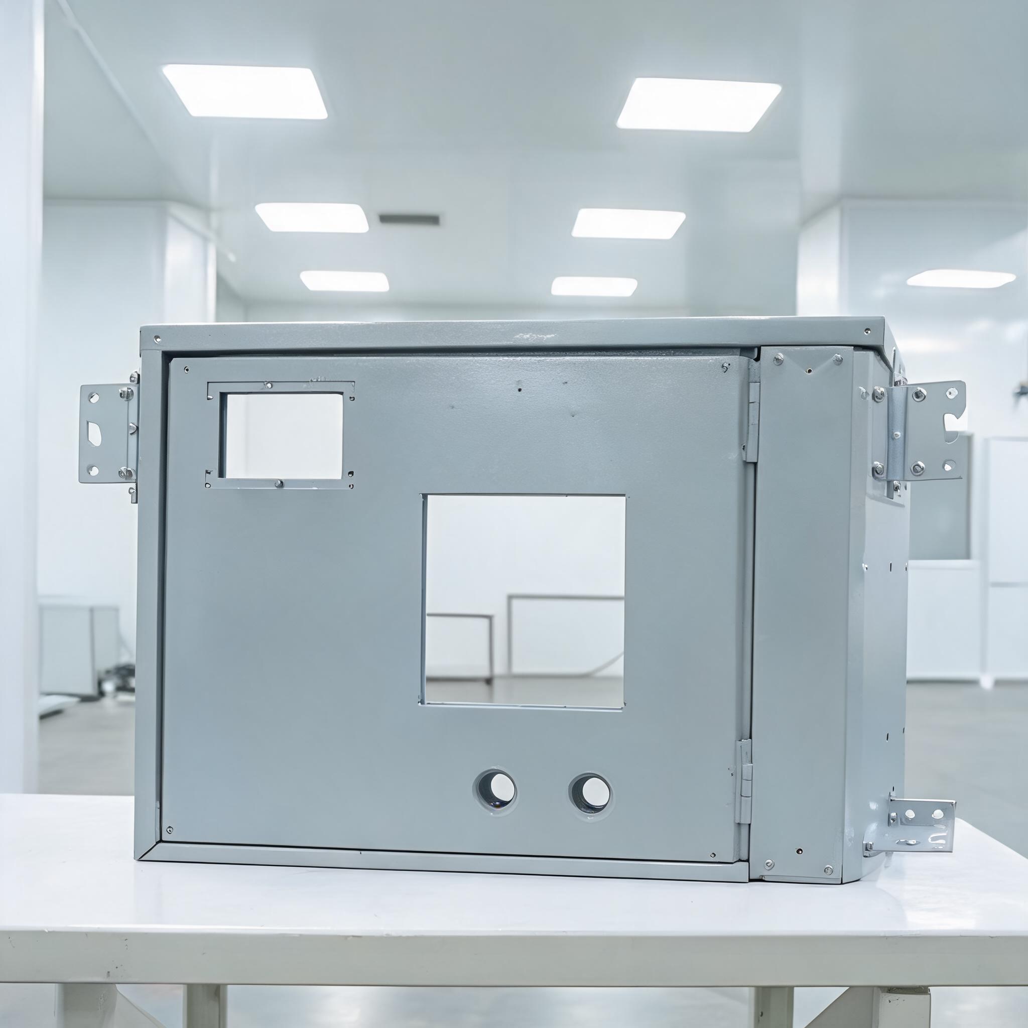
This article explains what a single-line enclosure workflow looks like, why it changes the risk profile for buyers sourcing electrical cabinets, control panels, equipment housings, consoles, instrument panels, and machine guards, and what to verify at each gate of the qualification trail.
Key takeaways
- Enclosure quality is decided by process integration: cutting, bending, welding, and coating on one line with one QA trail.
- Each outsource hand-off adds an accumulated tolerance and a new place for the spec to drift.
- Laser cutting, CNC punching, bending, and MIG/TIG/spot welding are only as good as the sequence that links them.
- Drawings, tolerance risk, sample release, FAI, and a QC photo pack give a buyer documented checkpoints at every gate.
In this article
- Why stitched vendors accumulate tolerance
- The one-stop flow, step by step
- Where welding and coating change the part
- The QA trail: drawing review to FAT
- What to verify at each gate
- FAQ
Why stitched vendors accumulate tolerance
When a buyer splits a job across a cutter, a fabricator, a welder, and a coater, each supplier interprets the drawing differently. A ±0.2 mm bend allowance applied by one shop and a different figure applied by the next do not average out — they stack. By the time the assembly reaches final coat, the cumulative deviation can exceed the clearance a door hinge or a backplate gasket was designed around.
The bigger loss is not dimensional. It is the accountability trail. If a QC photo pack shows a warped door, the cutter says the bend was the problem; the bender says the weld pulled it; the welder says the fit-up was already off. Sorting out which shop owes you a rework or a replacement costs more than the parts.
A single line changes the economics of that argument. One supplier holds the drawing, sets the tolerance on each operation, and answers for the finished assembly.
The one-stop flow, step by step
In an integrated workflow, the part moves through these gates without leaving the same production floor and the same documentation system.
Drawing review
Before any metal is cut, the drawing is checked for callouts that are hard or impossible to hold — a bend relief that fights a weld, a hole pattern too close to a folded edge, a finish spec that will not survive a forming operation. This review produces a redlined drawing and a list of queries returned to the buyer. It is the cheapest place to change a design; every later stage gets more expensive.
Cutting and punching
Flat blanks come off either the laser or the punch, depending on geometry and volume. A TruMatic 6000 covers laser cutting; CNC punching on Amada equipment handles repetitive hole patterns, louvers, and forming jobs that would otherwise consume laser time. The choice matters to a buyer because it affects edge quality, tool-mark visibility, and cost at volume — not because one route is universally better.
Bending
Bending converts the flat pattern into the enclosure's three-dimensional shape. Bend allowance, back-gauge position, and tool radius must match the pattern the cutter produced. When cutting and bending sit on the same line, the two operations share the same drawing revision, which is why the tolerance stack stays predictable.
Welding
MIG, TIG, and spot welding each suit different joints. Spot welding is common on cabinet seams and brackets where distortion must stay low. MIG handles heavier structural joints; TIG is used where a clean, controllable bead matters, such as visible stainless faces. Heat input is the enemy of squareness — a weld schedule that is too aggressive on a large panel will pull it, and no amount of downstream straightening fully returns it.
Coating
Powder coating is the last major operation and the one with the most visible consequences. Pre-treatment, film thickness, cure schedule, and masking all interact with weld quality and surface preparation. Coat applied over an improperly cleaned weld will fail at the weld, not at the panel — which is exactly why the coater should sit inside the same QA trail as the welder.
Assembly
Hardware, gaskets, hinges, fans, and sub-assemblies are fitted last. At this stage, the accumulated tolerance either allows the door to close cleanly and the gasket to seal, or it does not. Because the whole flow shares one set of fixtures and one drawing revision, the assembly stage is where integration is confirmed or exposed.
Where welding and coating change the part
Two operations deserve special attention from buyers because they change the part in ways that a dimensional check alone will not catch.
| Operation | What it controls | What can go wrong if separated from the line |
|---|---|---|
| MIG / TIG / spot welding | Joint integrity, squareness, distortion control | Heat pulled out of sequence; out-of-square panels; rework blamed on the bender |
| Powder coating | Corrosion protection, finish adhesion, color consistency | Coating over contaminated welds; chipping at folded corners; mismatch between batches |
| Bending | Angles, radii, flatness | Bend allowance inconsistent with the cut pattern; doors that will not sit flat |
| Laser cutting / CNC punching | Hole position, edge quality, blank accuracy | Tool-path and forming disagreements; hole patterns drifting across a batch |
The table is not an argument that outsourcing is always wrong. It is an argument that the buyer should know where each operation sits on the accountability chain before approving the first article. See how integrated cutting, bending, and welding are described in our Custom Sheet Metal Enclosure Fabrication workflow, and how welded joints and finishes are handled in Custom Welding Fabrication Services and Custom Powder Coating Services.
The QA trail: drawing review to FAT
Buyers sourcing complete enclosures are not just buying a set of processes — they are buying evidence that each process stayed on spec. On an integrated line, that evidence can be recorded as a single sequence.
- Drawing review: redlined drawing, open questions, and a jointly agreed revision before cutting.
- Tolerance risk assessment: the operations with the tightest stack (usually bend angle, weld distortion, and fit-up) are flagged and monitored.
- Sample release: a first-off part is produced and reviewed against the drawing before batch production is authorized.
- First Article Inspection (FAI): dimensions, finish, and hardware are recorded on the production sample.
- QC photo pack: photographs of critical features, welds, and finish are assembled as a batch record.
- FAT: final acceptance testing confirms the assembly performs as specified before shipping.
The sequence matters. FAI taken before the drawing is frozen is a measurement of the wrong part; a photo pack assembled after the parts are packed is documentation of the wrong moment. An integrated line keeps these gates in order and keeps the evidence attached to the same revision.
What to verify at each gate
For buyers comparing an integrated supplier against a stitched supply chain, the practical checklist is short.
- Who owns the drawing revision, and does the same revision reach the cut program and the brake?
- Which operations are performed in-house, and which are subcontracted? If subcontracted, what is the inspection step on return?
- Is the weld schedule tied to the material thickness and joint type, or applied uniformly?
- Does the coating line document pre-treatment and cure, and does the record link back to the weld batch?
- Does the FAI cover the features that define fit — hinge positions, panel flatness, hole pattern — or only overall dimensions?
- Can the QC photo pack be traced to the specific batch and drawing revision?
Where the answer to any of these is unclear, that is a specific question to raise with the supplier before releasing the first article — not an assumption to carry into production.
FAQ
Is a single-line enclosure workflow always better than splitting the job?
Not automatically. A tightly managed multi-vendor chain can hold tolerance if the drawing revision and inspection plan are shared. The advantage of a single line is that the tolerance stack and the accountability trail stay in one place, which usually shows up as fewer fit-up surprises at assembly and a shorter path to rework if something is off.
What is the difference between an FAI and a QC photo pack?
An FAI records measured characteristics of the first article against the drawing — dimensions, finish, hardware. A QC photo pack is a visual batch record showing critical features, welds, and finish as produced. They answer different questions: the FAI answers whether the part meets spec; the photo pack answers whether the batch was built the way the approved sample was.
Why does powder coating finish depend on the welding step?
Coat adhesion is affected by what is underneath it. A weld with porosity, spatter, or surface contamination gives the pre-treatment and powder a poor substrate, and the coating is most likely to fail along that weld. Keeping coating on the same line as welding means surface preparation and weld quality can be inspected together rather than argued about after shipping.
What quality standards apply to enclosure fabrication?
For automotive-adjacent and other regulated programs, IATF 16949:2016 is a common quality management reference. Whether it applies to your enclosure order depends on the program and the supplier's certification scope — confirm the certificate and its scope directly with the supplier rather than assuming it covers every product line.
Putting the line to work on your next enclosure
Enclosure programs rarely fail because a single machine could not hold tolerance. They fail because the tolerance moved between four vendors and nobody owned the result. An integrated line — drawing review, cutting, bending, welding, coating, FAI, and a QC photo pack under one quality system — gives the buyer one drawing revision, one inspection plan, and one point of contact from panel to assembly.
If you are sourcing complete enclosures and want the process flow matched to your drawing, review the integrated workflow on this page or send the drawing set for a tolerance review before the first article is cut.