
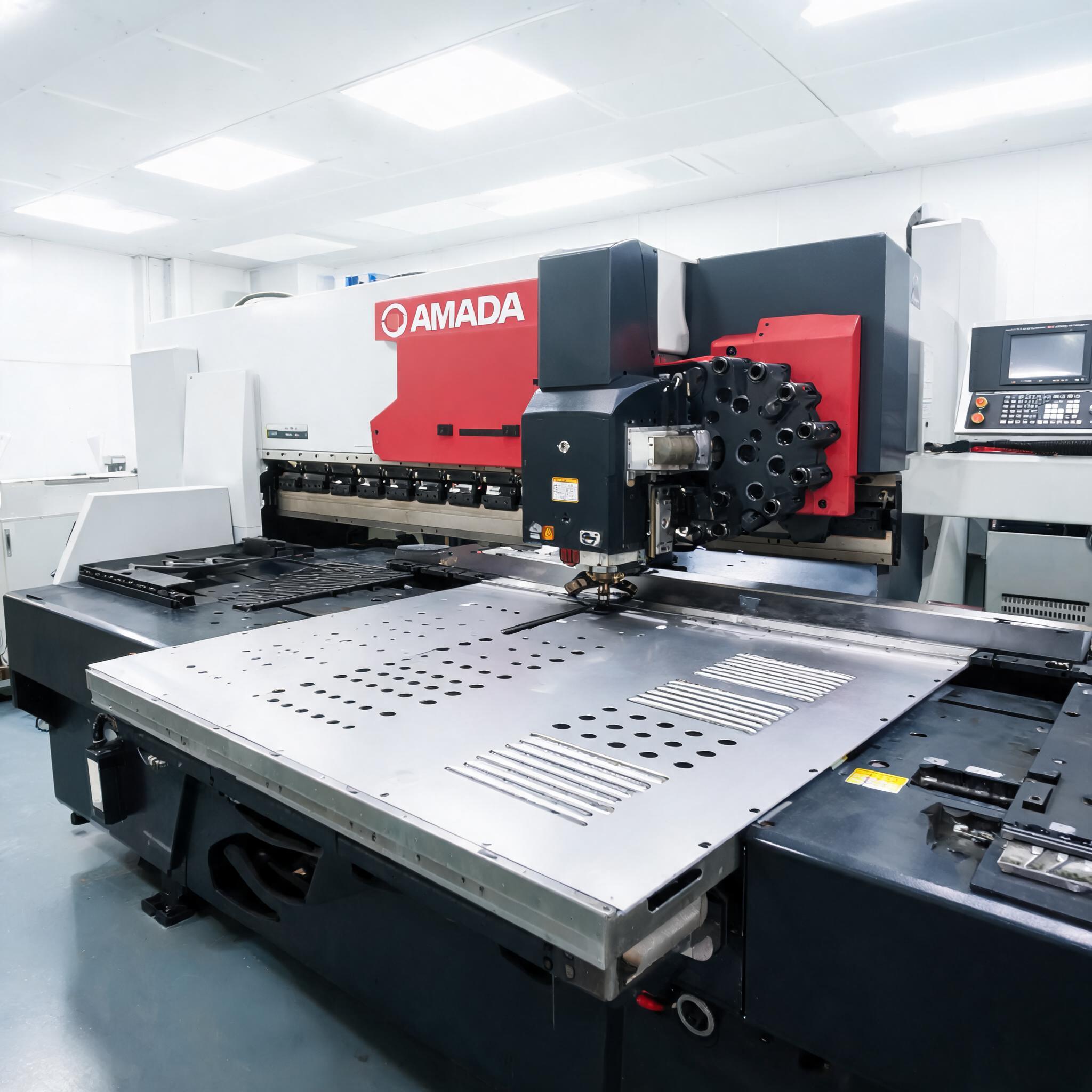
A practical RFQ-preparation guide for buyers sourcing stamped samples. Covers the drawing details that decide feasibility — formed feature callouts, bend reliefs, hole-to-form distances, material spec — and the file formats (STEP, IGES, DXF, DWG, PDF) that let a stamping supplier review and quote without back-and-forth.
Prototype Stamping RFQ Guide
A stamping supplier can only quote a prototype as fast as the drawing package allows. When a formed feature is called out loosely, when a bend relief is missing, or when a hole sits too close to a form, the supplier has to stop and send questions back. Every round of clarification adds days before a sample is cut. Most of the delay is avoidable, and it is decided before the RFQ is ever sent.
This article covers the drawing details that determine whether a stamped sample is feasible to quote directly: formed feature specifications, bend reliefs, hole-to-form distances, material specification, and file formats. It is written for buyers preparing a prototype sheet metal stamping RFQ, not for tool designers.
Key takeaways
- Formed features — louvers, lances, ribs, embossing, countersinks, V-cuts — need defined geometry, direction, and function, not just a symbol.
- Bend reliefs and hole-to-form distances are the two most common reasons a drawing cannot be quoted as-is.
- Material spec should state grade and temper or condition, not just a family name.
- Send STEP or IGES for 3D form and a DXF or DWG for flat-pattern detail; a PDF drawing carries the tolerances and notes that files alone cannot.
What the supplier actually reviews
When a quote request arrives, the drawing is checked against two things: whether the part can be formed at the stated thickness and geometry, and whether the tolerances can be held in a prototype tool. That review looks at formed features, bend radii and reliefs, hole positions relative to forms, and material. Anything left open becomes a question back to you.
The goal of the drawing is to let that review finish in one pass. Note that the drawing review and tolerance risk assessment happen before tooling is committed, so a complete package also protects you from a sample that cannot be reproduced in production.
Formed feature specifications
Formed features are where a prototype drawing most often goes quiet. A symbol on a print is not a specification. For each feature, state the geometry, the direction, and the function it serves.
- Louvers — pitch, length, opening height, and orientation. Opening height relative to material thickness is a direct feasibility question.
- Lances — the intended engagement and the cut length, since a lance that carries a load behaves differently from one used as a stop.
- Ribs — height, width, direction, and whether they are for stiffness only. Rib height relative to thickness determines how the form is developed.
- Embossing — depth, perimeter, and whether it is functional or cosmetic. Cosmetic embossing can still need a defined tool approach.
- Countersinks — the screw or rivet standard it must match, plus the included angle and depth.
- V-cut — the angle and the position of the cut, including which face it enters from.
If a feature is drawn but its function is unstated, the supplier may still quote it, but the risk of a costly assumption rises. A one-line note — "lance acts as a cable stop" — removes that ambiguity at no cost to you.
Bend reliefs and radii
A bend relief is a small cut or notch that separates a bend from an adjacent wall or flange so the material does not tear or distort. It is frequently omitted on prototype drawings because the CAD model looks correct without it. Ask for the relief width and depth relative to material thickness to be shown or noted.
Inside bend radii matter just as much. If the drawing shows a sharp inside corner, the supplier must either propose a radius or flag the limitation. For prototype work, note the intended radius range rather than a single value, so the tool can be built within a workable window.
Hole-to-form distances
Holes placed close to a bend or formed feature are a common source of rework. When a hole is too near a form, the material stretches during forming and the hole distorts. State the minimum distance you can accept from the hole edge to the form, or confirm that the drawing's distances are intentional.
Similarly, holes near a bend should note whether they are pierced before or after forming. This single note tells the supplier how the tool sequence must be arranged and whether the as-drawn position is achievable.
Material specification
A material callout of "stainless steel" or "aluminum" is not enough to quote confidently. Grade and condition or temper drive formability, springback, and the tooling approach.
| What to state | Why it affects the quote |
|---|---|
| Grade, e.g. 304 / 5052 | Determines strength and forming behavior |
| Temper or condition | Springback and bend allowance change with hardness |
| Thickness with tolerance | Forming feasibility and tool clearance |
| Surface or finish requirement | Affects handling and any post-form operation |
| Standard, if applicable | Keeps the sample aligned with later production |
If a substitute grade is acceptable, say so. It can shorten the time to a sample, and it gives the supplier a fallback if the specified material is not available in prototype quantity.
File formats to send
Send the native CAD model, the flat-pattern file, and the drawing. Each carries information the others cannot.
| Format | What it provides |
|---|---|
| STEP | 3D geometry and formed shape |
| IGES | Alternative 3D surface geometry |
| DXF | Flat pattern outline and hole positions |
| DWG | 2D drawing with dimensions and layers |
| Drawing with tolerances, notes, and revisions |
Confirm the flat pattern matches the formed model. If the flat pattern was generated with the wrong bend allowance, it will conflict with the STEP file, and the supplier has to resolve the discrepancy before quoting. A revision block on the drawing, and a file name that matches that revision, prevents quoting the wrong version.
For parts that also need cut edges or blank preparation, it can help to compare the routes available. Our Custom Laser Cutting Services cover flat blank and trim work, while the forming of louvers, ribs, embossing, and bends falls under Custom Sheet Metal Stamping Services. Knowing which operations the sample needs helps you organize the package for the right process.
Where quality systems enter the picture
For buyers in automotive or other regulated supply chains, the supplier's quality system is part of the quotation decision. IATF 16949:2016 is the relevant standard in that sector. Ask whether the supplier holds it and whether the prototype sample will be produced under that system, including documentation of the inspection plan. This is a two-minute question during RFQ preparation that avoids a re-sourcing problem later.
A workable RFQ checklist
- 3D model in STEP or IGES.
- Flat pattern in DXF, consistent with the model.
- 2D drawing in PDF or DWG with tolerances, notes, and revision.
- Formed features specified with geometry, direction, and function.
- Bend reliefs and inside bend radii shown or noted.
- Hole-to-form distances stated, plus pierce-before-or-after-forming.
- Material grade, condition, thickness, and any acceptable substitute.
- Quantity for the sample run and the target application.
FAQ
Can I send only a STEP file and no drawing?
A STEP file shows the formed geometry, but it carries no tolerances, material conditions, or notes on function. The supplier can review the shape, yet will still need those details before quoting. Sending STEP together with a marked-up PDF is the fastest combination.
My flat pattern was generated automatically. Is that acceptable?
It is acceptable if the bend allowance used matches the material and radii in the model. When they disagree, the supplier will flag the mismatch. State which values were used so the difference can be checked rather than guessed.
How close can a hole be to a bend?
There is no single number that applies to every material and thickness. The practical approach is to state the minimum distance your design can tolerate, then let the supplier confirm feasibility against the actual material. This keeps the discussion on your requirement instead of a generic rule.
Do I need to specify surface finish at the prototype stage?
Only if the finish affects the function or the forming operation. Otherwise, note it so the sample reflects the intended production route, and confirm any post-form operation with the supplier before tooling is committed.
A drawing package that answers the form-feature, relief, hole-distance, and material questions in one pass is the difference between a quote in days and a quote after several email rounds. If you are preparing a prototype sheet metal stamping RFQ, send the model, the flat pattern, and the marked drawing together, and note the quantities and application so the supplier can review feasibility against the real requirement.