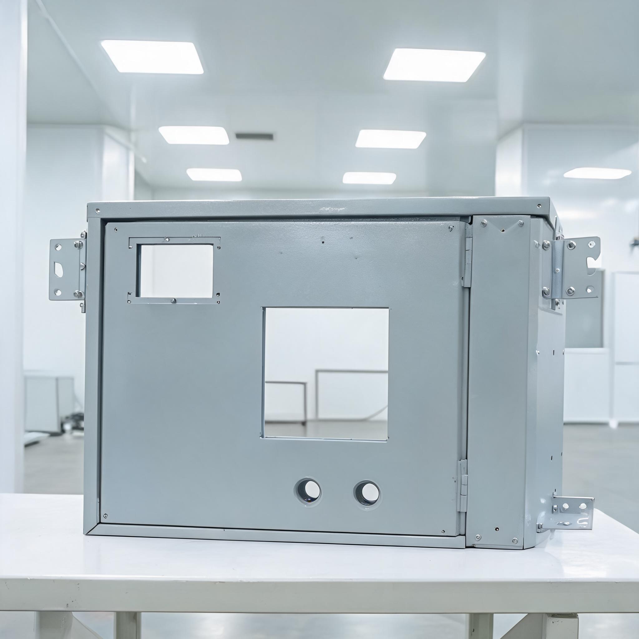
A practical engineering guide to the tolerances that determine whether a sheet metal chassis works—mounting hole patterns, card-guide flatness, rail parallelism, and grounding contact points—and how welding distortion is controlled through fixturing, sequence welding, and low-heat-input laser welding.
Four interface tolerances decide whether a sheet metal chassis works: the mounting hole pattern, the flatness of the card guides, the parallelism of the rails, and the contact geometry at the grounding points. Welding distortion is the main threat to all four, and it is controlled through fixturing, welding sequence, and low-heat-input processes rather than through inspection alone.
Key takeaways
- Mounting hole patterns and card-guide flatness are the tolerances most often implicated when boards bind or connectors misalign.
- Rail parallelism is a stack-up dimension across the full weldment, not a single-part measurement.
- Grounding contact points lose effectiveness when distortion pulls mated surfaces apart or changes contact pressure.
- Welding-induced shrinkage, not raw cutting accuracy, is the dominant distortion source in a welded chassis.
- Fixtures and sequence welding set the weldment geometry before inspection; low-heat-input laser welding limits the distortion the fixture must hold.
In this article
- Which tolerances actually decide chassis function
- Mounting hole patterns and connector alignment
- Card guides, rail parallelism, and slot-to-slot fit
- Grounding contact points
- Why welding-induced distortion is the real risk
- Fixtures, sequence welding, and low-heat-input processes
- What to qualify in a FAT record and QC photo pack
Which tolerances actually decide chassis function
A sheet metal chassis is a set of interfaces. Each interface has a tolerance that determines whether the next assembly step succeeds or fails. For electronics and industrial chassis, four interfaces carry most of the functional risk:
- Mounting hole pattern. Hole-to-hole spacing and hole position relative to datums govern board, connector, and bracket alignment.
- Card-guide flatness. The guide surface must be flat enough that a board slides without tilt and seats fully.
- Rail parallelism. Opposing rails must stay parallel over their length so board slots line up across the chassis.
- Grounding contact points. Contact surfaces must mate with enough pressure and cleanliness to carry the intended ground path.
These are not independent. Distortion that opens a rail gap also shifts hole positions and can separate grounding surfaces. That is why chassis geometry is best treated as a welded assembly dimension, not a collection of individual part dimensions.
Mounting hole patterns and connector alignment
Hole pattern tolerance is usually specified as position tolerance relative to defined datums, with a maximum material condition or a projected tolerance zone where fasteners pass through thick stacks. The functional question is not the diameter of a single hole; it is whether a board, backplane, or connector can be fastened across all its holes at once.
When a chassis is welded after holes are punched or laser-cut, weld shrinkage moves those holes relative to each other. A pattern that was correct on the flat blank can drift out of position once the weldment cools. Buyers should confirm:
- Which datums the hole pattern references: a primary datum on the base, or a functional datum at the connector interface?
- Whether the pattern tolerance is applied before or after welding.
- Whether connector cutouts are dimensioned to the same datum as the mounting holes they must align with.
Card guides, rail parallelism, and slot-to-slot fit
Card-guide flatness controls how a PCB enters and seats. A guide that bows along its length forces the board to tilt, which increases insertion force and stresses edge connectors. Rail parallelism controls whether a board seated in one slot lines up with the corresponding slot on the opposite rail across the full chassis width.
Both are stack-up dimensions. They depend on the flatness of each rail, the squareness of the end plates or brackets that hold them, and the accumulated effect of welds along the chassis length. A useful practice is to define rail parallelism as a maximum deviation between opposing rails measured at the front and rear of the chassis, rather than as a single rail flatness callout.
For chassis with multiple card slots, slot-to-slot pitch matters as much as absolute position: if pitch varies, boards and filler panels will not interchange between slots. Pitch variation is a common symptom of welding sequence that alternately pulls one end of the chassis and then the other.
Grounding contact points
Grounding contact points are functional surfaces, not cosmetic ones. They may be dedicated studs, masked contact areas, or mating flanges between chassis sections. Their performance depends on contact area, contact pressure, and surface condition. Distortion affects all three: it can reduce the pressure holding two surfaces together, open a gap that interrupts the path, or move a stud so that the grounding lug no longer seats flat.
Where a chassis uses masked or plated contact zones, the fabrication sequence matters. Weld heat near a masked zone can damage the mask or change the surface, and post-weld grinding can remove the very surface the ground path depends on. Buyers should confirm how contact zones are protected through welding, cleaning, and finishing, and how they are verified before shipment.
Why welding-induced distortion is the real risk
Cutting and forming tolerances are relatively predictable: a fiber laser or punch press holds a hole pattern to a known tolerance, and a press brake holds a bend angle within a stated range. Welding introduces a different class of error. Localized heating and subsequent cooling cause shrinkage, and shrinkage pulls the weldment out of the geometry the fixture established.
Distortion shows up in characteristic ways:
- Angular distortion at fillet and butt joints, which tilts end plates and changes rail squareness.
- Longitudinal shrinkage along a seam, which shortens the chassis and shifts hole patterns near the weld.
- Buckling or oil-canning of thin panels, which changes card-guide flatness.
- Weld draw across an assembly, which accumulates over a sequence of welds and can close or open rail spacing.
Because distortion accumulates during welding, an inspection after the fact can detect it but cannot correct it economically. The countermeasures have to act during fabrication.
Fixtures, sequence welding, and low-heat-input processes
Three countermeasures work together. None of them replaces the others.
Deformation control fixtures
A deformation control fixture holds the weldment in its functional geometry during welding. It locates on the datums that matter—base, rail mounting faces, hole pattern—and constrains the part so that shrinkage works against the fixture rather than against the final shape. Fixture design matters: clamping too far from a weld does little to control local distortion, while clamping rigidly across a long seam can introduce its own residual stresses.
Sequence welding
Sequence welding distributes heat so that shrinkage is balanced. Instead of completing one seam and then moving to the next, the welder alternates positions—opposite sides, alternating ends, backstep or skip welding—so that each pass pulls against a previously cooled joint rather than adding to a one-directional draw. The specific sequence depends on the weldment; the principle is to avoid concentrating heat on one side and to allow cooling between passes.
Low-heat-input laser welding
A laser welding robot with low heat input is a practical option for thin-sheet distortion control. Because the heat-affected zone is narrow and total heat input per unit length is low compared with conventional arc welding, there is less shrinkage to control. This reduces the load on the fixture and makes sequence welding more forgiving, but it does not eliminate the need for either. Laser welding suits thin-gauge chassis where distortion per unit of heat input is highest.
| Interface | What it controls | Typical distortion effect | Primary countermeasure |
|---|---|---|---|
| Mounting hole pattern | Board, backplane, connector fastening alignment | Pattern shift after weld shrinkage | Functional datums and post-weld dimensional check |
| Card-guide flatness | Board entry and full seating | Bowing of thin panels and rails | Fixturing and balanced weld sequence |
| Rail parallelism | Slot-to-slot alignment across chassis width | Accumulated weld draw over assembly | Sequence welding and low-heat-input process |
| Grounding contact points | Ground path continuity and contact pressure | Mated surfaces pulled apart or mask damage | Weld-zone protection and post-weld verification |
What to qualify in a FAT record and QC photo pack
Because distortion is a process outcome, the documents that matter are records of how the process was controlled and what was measured, not just a final dimensional pass. A useful acceptance package for a welded sheet metal chassis typically includes:
- FAT records covering the functional interfaces: hole pattern position relative to stated datums, rail parallelism at front and rear, card-guide flatness, and grounding contact verification.
- QC photo pack showing the welded assembly in the fixture, weld sequence marks or weld maps, contact-zone protection before finishing, and measured results with the gauge or CMM setup visible.
- Material and process traceability for the sheet and any specified surface treatment.
Where a supplier maintains a quality management system certified to IATF 16949:2016, the certification indicates that a documented quality system is in place for the applicable scope. It does not, by itself, prove that a specific chassis meets a specific tolerance. Ask for the interface measurements on the parts you are buying, and confirm that the supplier will include them in the FAT record.
FAQ
Should hole pattern tolerance be called out on the flat blank or on the welded assembly?
On the welded assembly, referenced to functional datums. Blank-level tolerances are useful for upstream process control, but weld shrinkage shifts hole positions, so the acceptance dimension for a buyer is the post-weld pattern. Confirm with the supplier which datums are used to inspect the pattern.
Is laser welding enough to prevent distortion without a fixture?
No. Low heat input reduces the amount of shrinkage, which lowers the load on the fixture, but the weldment still needs to be held in its functional geometry during welding. Fixturing, sequence welding, and low-heat-input processes are complementary; using one alone leaves the other distortion sources unmanaged.
How should rail parallelism be specified?
As a maximum deviation between opposing rails, measured at defined stations such as front and rear of the chassis, and sometimes at mid-length for long chassis. A single flatness callout on one rail does not capture the parallelism that determines slot-to-slot fit.
What should be in a QC photo pack for a welded chassis?
Photos of the assembly in its fixture, the weld sequence or weld map, contact-zone protection before finishing, and the measured interface results with the inspection setup visible. Photos should document process control and measurement, not only the finished appearance.
Next step
If your chassis has boards, rails, or connectors that must align under load, the place to start is the interface tolerance list: which datums, which measurements, and which records. Review Custom Sheet Metal Enclosure Fabrication for chassis and enclosure fabrication, and Custom Welding Fabrication Services for welded assemblies with fixturing, sequence welding, and documented inspection. Share your drawing, datums, and the interfaces you need verified, and confirm which measurements the supplier will include in the FAT record.