
A technical explainer for B2B buyers comparing plate-cutting suppliers. It covers what determines achievable tolerances and edge quality on custom cut steel plate, how laser and punch processes differ in edge formation, and what to state on drawings so quoted tolerances match what you can actually inspect and accept.
Two suppliers can quote the same part from the same DXF and produce plates that behave very differently on your assembly line. The gap is usually not machinery class — it is how each supplier reads tolerances, which cutting process it assigns to which feature, and whether anyone confirmed from your drawing what actually counts as an acceptable edge. This article explains what drives both, and what to put on a drawing so the quote, the part and your inspection all refer to the same thing.
Key takeaways
- Tolerances and edge quality are confirmed feature by feature against the drawing, not assumed from a general capability table.
- Laser and punch form edges differently; that difference matters for burrs, heat-affected zones and subsequent finishing.
- Material type — low-carbon steel, stainless or aluminum — changes how a cut edge behaves and how it should be finished.
- A drawing that separates critical features from cosmetic edges gets quoted more accurately than a fully tight, undifferentiated title block.
- Drawing review and tolerance risk assessment should happen before a quote, not after the first rejected lot.
Why "typical tolerance" is the wrong question
Buyers often ask suppliers for "the tolerance you can hold on custom cut steel plate." That number is not a property of a machine. What a supplier can hold depends on material, plate thickness, part geometry, the process applied to a specific edge, and how the feature is measured. A generous tolerance on one contour and a tight tolerance on a hole pattern sit in the same part and are not produced or inspected the same way.
The workable version of the question is: "Given these features, this material and this thickness, what tolerance can you confirm for each one, and how will it be measured?" Any figure quoted before that conversation is a planning assumption, not a commitment. Where we supply custom cut steel plate, typical tolerances are confirmed per drawing review rather than published as a single blanket figure, because that is the only way the number survives to inspection.
What actually drives achievable tolerance
Four variables decide most of the outcome:
- Feature type. Outside profiles, internal cutouts, hole positions and hole diameters are measured against different datums. A tolerance that is easy on an outside profile can be tight on a hole-to-hole pitch.
- Material and thickness. Low-carbon steel, stainless and aluminum respond differently to the same cutting energy. Stainless and aluminum tend to need more attention to dross and edge condition; thicker plate narrows the window on fine features.
- Process assignment. A laser can cut contours and fine geometry; a punch can deliver repeatable hole patterns at speed. Assigning the right process to the right feature is where a supplier's engineering judgment shows up.
- Datum and reference scheme. If the drawing does not say which face or edge is the datum, two inspectors will get two answers from the same good part.
How laser and punch differ, in practice
Laser cutting and punching are not interchangeable; they leave different edges and suit different features.
| Attribute | Laser cutting | Punching |
|---|---|---|
| Edge character | Narrow kerf; a heat-affected zone near the cut face; edge may show slight discoloration or dross depending on material and parameters. | Sheared edge with a characteristic break; burr direction is process-dependent and worth specifying. |
| Best suited to | Contours, internal profiles, fine or changing geometry, low-to-mid volume work without dedicated tooling. | Repeatable hole patterns, standard shapes, higher-volume runs where tooling pays back. |
| Practical trade-off | Slower on simple dense patterns; can be the right call for complex outlines. | Tooling and setup considerations; not ideal for one-off contours. |
| Edge prep note | Confirm whether the visible edge is acceptable as-cut or needs deburring or finishing. | Confirm burr-side orientation and whether an edge finish is required after punching. |
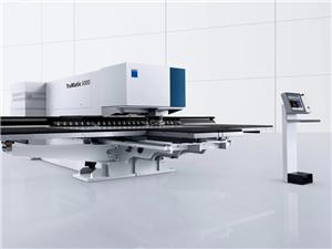
A combined laser-and-punch platform such as the TRUMPF TruMatic 6000 lets one setup cover both feature types, which reduces the number of times a plate is re-referenced. That matters for positional tolerance: every additional setup is another chance for datum drift.
Edge quality: what "good" means for your part
"Good edge quality" is not a fixed grade. It is a functional statement: the edge is acceptable for what happens next. That depends on the downstream step — welding, powder coating, forming, or exposed decorative service.
- If the edge will be welded, specify whether mill scale, oxide or a heat-affected zone is acceptable at the weld face.
- If the part will be coated, specify the surface condition required before coating, including whether any burr or dross is permitted.
- If the edge is exposed in service, specify whether it needs deburring or a defined edge radius.
- If the part is handled by operators, specify whether the as-cut edge must be safe to handle, since this drives whether deburring is included in the scope.
When a drawing does not state these, suppliers fall back on their default — and the default may not match the step you had in mind. Stating the downstream operation is often more useful than naming a burr height, because it tells the supplier what the edge has to survive.
What to put on the drawing
A drawing that a supplier can quote accurately usually contains:
- A clear title block naming material (low-carbon steel, stainless, aluminum) and thickness, with the specification standard where one applies.
- A defined datum scheme: which edge or face is the reference, and how holes and profiles are dimensioned from it.
- Feature-by-feature tolerances, distinguishing critical features from cosmetic ones rather than applying one tight tolerance to everything.
- Edge callouts: as-cut acceptable, deburred, defined radius, or a note about the downstream process (weld, coat, form).
- Burr-side orientation where it matters to assembly.
- A note on any feature the supplier should flag if it cannot be held, rather than silently producing to a looser condition.
Checklist-style callouts on the drawing save quoting time and reduce the risk of a part arriving to one interpretation and being inspected to another.
File formats
STEP and IGES carry 3D geometry; DXF and DWG carry 2D profiles; PDF is useful for notes, revisions and stamped dimensions. Sending the native 2D profile along with the PDF drawing gives the supplier both the geometry and your intent. When both are present, confirm which one takes precedence so any discrepancy is resolved before cutting.
How a quote should be built
A quote that survives to production is built from a drawing review first. The useful sequence is:
- Review the drawing and identify each feature that carries a tolerance.
- Run a tolerance risk assessment: flag features where the stated tolerance, material, thickness or edge callout may not be achievable as drawn.
- Assign process — laser, punch or a combination — to each feature based on geometry and quantity.
- Confirm typical tolerances against the drawing and state which ones are feasibility-checked versus assumed.
- Quote the part as reviewed, with any exceptions in writing.
Discussions about feasibility are cheaper at quoting than at first article inspection. For projects under a quality system such as IATF 16949:2016, this review is also part of documenting that the process is under control, not just that the part passed once.
Documents that travel with the plate
Material traceability matters for many buyers. Where required, an MTR can accompany the shipment, connecting the plate to its heat or lot. If traceability is mandatory for your application, state it in the RFQ — it influences how material is issued and how the finished plate is packed and marked.
If tighter positional tolerances are part of the picture on machined features, the companion article on CNC machining tolerances and what B2B buyers should specify explains how IT grades map to inspection on cut and machined features.
Common mistakes to avoid
- Applying one tight general tolerance to the whole drawing instead of the features that need it.
- Leaving edge condition unspecified, then rejecting a part for a burr that was never called out.
- Sending only a PDF when the supplier needs the geometry file to program the cut.
- Not naming the downstream process (weld, coat, form), which is what actually defines the required edge.
- Treating a first-article result as proof the batch will hold the same tolerance without a stated inspection method.
Where our capabilities fit
We have been sourcing and producing cut metal parts since 2009 and work with the TRUMPF TruMatic 6000 for combined laser and punch processing on low-carbon steel, stainless and aluminum. Files can be sent as STEP, IGES, DXF, DWG or PDF, and MTRs are available. Every project starts with drawing review and tolerance risk assessment so the quoted tolerance and edge condition are the ones that will actually be inspected.
If you want to compare this with our fabrication scope, our custom laser cutting services page sets out the process, and for formed parts our custom sheet metal stamping services page covers the secondary operation.
FAQ
Can you quote tolerances before seeing the drawing?
We can give a planning range for a given material and thickness, but the committed figure comes from drawing review. Send the drawing and we will confirm typical tolerances per feature rather than a single number for the whole part.
Will laser and punch parts have the same edge?
No. The two processes leave different edge characteristics, and which is right depends on the feature and the downstream operation. State both in the RFQ and we will assign process accordingly.
Can I get material traceability with the order?
Yes, an MTR is available. Tell us at the RFQ stage if traceability must be documented, since it affects material issue and marking.
Do you require native CAD files or is a PDF enough?
A PDF drawing is useful for notes and revisions, but the geometry file (DXF, DWG, STEP or IGES) is what the cutting program is built from. Sending both avoids interpretation errors.
Next step
Send the drawing, material and thickness, and the downstream process for each edge. We will review the drawing, run a tolerance risk assessment, and come back with typical tolerances confirmed per feature plus any feasibility notes you need to quote internally. If anything on the drawing is ambiguous, we will flag it before cutting rather than after.