
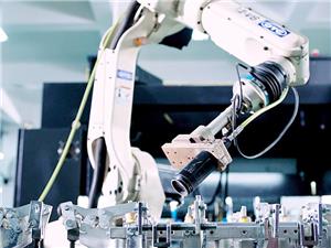
Learn how rapid sheet metal prototyping turns CAD files into functional metal parts in days, not weeks. This guide covers the process, key technologies, cost factors, and how to evaluate a supplier for your next project.
RAPID SHEET METAL PROTOTYPING GUIDE
- Rapid sheet metal prototyping can deliver functional first articles in 3–10 business days, depending on part complexity and finish requirements.
- Laser cutting, CNC punching, and press brake forming are the core processes; combining them reduces tooling cost and lead time.
- Material selection, tolerances, and surface finish directly affect speed and cost—knowing these trade-offs helps you get a better quote.
- Evaluating a supplier's equipment list, in-house capabilities, and quality control process is more reliable than reading marketing claims.
- DFM (Design for Manufacturability) feedback early in the process prevents costly rework and delays.
Why Rapid Sheet Metal Prototyping Matters
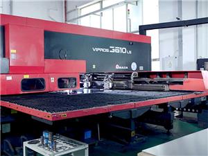
When you are developing a new product—whether it is an enclosure for medical equipment, a chassis for industrial electronics, or a bracket for automotive components—getting a physical part in your hands quickly is critical. Every day spent waiting for a prototype is a day lost in testing, validation, and time-to-market.
Traditional sheet metal fabrication often involves hard tooling: dedicated dies and molds that take weeks to manufacture and cost thousands of dollars. For low-volume prototypes and pre-production runs, that approach is both slow and expensive. Rapid sheet metal prototyping solves this by using flexible, programmable processes that eliminate or minimize hard tooling, allowing you to go from a CAD file to a finished part in days.
This article is written for procurement engineers, product designers, and sourcing managers who need to understand how rapid sheet metal fabrication works, what to expect in terms of lead times and costs, and how to choose a supplier that can deliver consistently.
The Core Process: From Drawing to First Article
Rapid sheet metal prototyping follows a structured workflow. Understanding each step helps you communicate requirements clearly and avoid surprises.
1. Design Submission and DFM Review
You send a 3D model (STEP, IGES, or native CAD format) along with a 2D drawing specifying critical dimensions, tolerances, and material. The supplier's engineering team reviews the design for manufacturability (DFM).
Common DFM feedback includes:
- Recommendations for bend radii that match available tooling
- Suggestions to reduce the number of setups or tool changes
- Advice on hole-to-edge distances to avoid distortion
- Material alternatives that improve formability or reduce cost
A good DFM review saves time and money. It is a sign of a competent supplier when they catch potential issues before cutting metal.
2. Material Selection
Material choice directly affects cost, formability, and lead time. Common materials for rapid sheet metal prototyping include:
| Material | Typical Applications | Formability | Relative Cost |
|---|---|---|---|
| Cold-rolled steel (CRS) | Enclosures, brackets, chassis | Good | Low |
| Galvanized steel | Outdoor enclosures, HVAC | Good | Low–Medium |
| Stainless steel 304/316 | Medical, food processing, marine | Moderate | Medium–High |
| Aluminum 5052/6061 | Lightweight enclosures, aerospace | Excellent | Medium |
| Copper / Brass | Electrical components, decorative | Moderate | High |
Most suppliers stock standard gauges (e.g., 16–22 gauge for steel, 0.040–0.125 in for aluminum). Non-standard gauges may add lead time.
3. Laser Cutting or CNC Punching
Once the design is approved and material is selected, the blank is cut. Two primary methods are used:
- Laser cutting (fiber or CO₂): Ideal for complex shapes, tight tolerances (±0.005 in typical), and any material thickness. No tooling needed—just a program file. This is the most common method for rapid prototyping.
- CNC punching: Faster for repetitive patterns and standard hole sizes. Uses a turret of tools; setup time is minimal but tool changes can add cost for non-standard shapes.
Many suppliers combine both: laser for the outer profile and internal cutouts, punch for repeated holes or louvers. This hybrid approach optimizes speed and cost.
4. Forming and Bending
The cut blank moves to the press brake. A CNC press brake uses a punch and die to bend the metal to the required angles. For rapid prototyping, the key is that the press brake operator can program the bend sequence directly from the 3D model without building dedicated dies.
Bend tolerances typically range from ±0.5° to ±1.0°, depending on material thickness and bend length. Tighter tolerances are possible but may require more setups or secondary operations.
5. Secondary Operations and Finishing
After forming, the part may need additional work:
- Deburring – removing sharp edges from laser cutting or punching
- Tapping / threading – adding threaded holes for assembly
- Welding – joining multiple pieces (if the part is an assembly)
- Surface finishing – powder coating, painting, anodizing, or plating
Finishing is often the longest step in the process. A simple powder-coat job may add 2–3 days; custom color matching or chemical treatments can take longer. For the fastest turnaround, consider using raw metal or a standard finish (e.g., clear anodize for aluminum, black oxide for steel).
6. Inspection and First Article Report
Before shipping, the supplier inspects the first article against your drawing. Critical dimensions are measured with calipers, micrometers, or CMM (coordinate measuring machine). A first article inspection report (FAIR) is typically provided, documenting measured values versus specified tolerances.
This step is non-negotiable for quality assurance. If you need a PPAP (Production Part Approval Process) level submission, confirm with the supplier in advance—it requires additional documentation and sampling.
Typical Lead Times for Rapid Sheet Metal Prototyping
Lead time depends on part complexity, material availability, and finishing requirements. Below are realistic estimates based on industry standards:
| Part Complexity | Material | Finish | Typical Lead Time (business days) |
|---|---|---|---|
| Simple bracket (1–2 bends, no holes) | CRS or aluminum | None (raw) | 3–5 |
| Moderate enclosure (multiple bends, cutouts, tapped holes) | Aluminum or steel | Standard powder coat | 5–7 |
| Complex assembly (welded, multiple parts) | Stainless steel | Custom paint or passivation | 7–10 |
These times assume the supplier has material in stock and the design is finalized. Any revision after cutting resets the clock.
Cost Drivers in Rapid Sheet Metal Prototyping
Understanding what drives cost helps you make design decisions that keep the project within budget.
- Setup time – Programming the laser cutter and press brake is a fixed cost per order. For prototypes, this is typically the largest cost component.
- Material cost – Stainless steel and specialty alloys cost more than CRS or aluminum. Thicker gauges also increase material cost.
- Number of setups – Each additional bend direction or tool change adds time. Designing parts with bends in the same direction reduces setups.
- Hole count and complexity – Laser cutting is indifferent to hole count (within reason), but punching with custom tools costs per tool change. For prototypes, laser is almost always the better choice.
- Finishing – As noted, finishing is a significant cost and time driver. Raw metal parts are cheapest and fastest.
- Tolerances – Standard tolerances (±0.010 in for linear dimensions, ±1.0° for bends) are cost-effective. Tighter tolerances require more inspection and may need secondary machining.
A typical rapid prototyping quote for a medium-complexity enclosure (e.g., 10" x 8" x 4", with 6 bends, 20 holes, and powder coating) might range from $200 to $600 per part for quantities of 1–10 pieces. Exact pricing should be confirmed with your supplier.
How to Evaluate a Rapid Sheet Metal Prototyping Supplier
Not all suppliers are equally equipped for rapid turnaround. Here are specific criteria to check:
Equipment
- Does the supplier have in-house laser cutting (fiber laser preferred for metal) and CNC press brakes?
- Are the machines modern (less than 5–7 years old)? Older machines have slower cycle times and lower accuracy.
- Do they have a CMM or other inspection equipment for first article verification?
Process
- What is their standard DFM review process? Do they provide feedback within 24 hours of receiving the CAD file?
- Do they offer a first article inspection report with every prototype order?
- How do they handle design revisions? Is there a clear change order process?
Communication
- Do they respond to technical questions within one business day?
- Can they provide a detailed quote that breaks down setup, material, and finishing costs?
- Do they speak your language (English, German, etc.) clearly enough for technical discussions?
Quality Certifications
- ISO 9001:2015 is the minimum standard for a reliable supplier.
- For medical or aerospace applications, look for ISO 13485 or AS9100.
- Ask for a sample of their first article inspection report to see the level of detail.
A supplier that checks all these boxes is more likely to deliver on time, within specification, and with minimal back-and-forth.
Common Mistakes to Avoid
Even with a capable supplier, mistakes in the design or communication phase can delay the project. Here are the most common ones:
- Over-specifying tolerances – Calling out ±0.005 in on every dimension when ±0.020 in would work adds cost and inspection time. Only tighten tolerances on critical features.
- Ignoring bend radius – Specifying a bend radius smaller than the material thickness can cause cracking or require special tooling. A general rule: inside bend radius should be at least 1× material thickness.
- Not accounting for springback – Sheet metal springs back slightly after bending. Good DFM feedback accounts for this; poor feedback may result in angles that are off by 1–2°.
- Forgetting about weld distortion – If your prototype is welded, expect some distortion. Design for post-weld machining or allow extra material for cleanup.
- Waiting until the last minute – Even rapid prototyping takes 3–10 days. Plan your project timeline accordingly, and build in a buffer for revisions.
When to Use Rapid Sheet Metal Prototyping vs. Other Methods
Rapid sheet metal prototyping is not the right solution for every situation. Here is a quick comparison:
| Method | Best For | Lead Time | Tooling Cost | Unit Cost (low qty) |
|---|---|---|---|---|
| Rapid sheet metal prototyping | 1–50 pieces, functional testing, form/fit | 3–10 days | Low–None | Medium |
| 3D printing (metal) | Complex geometries, internal channels | 2–7 days | None | High |
| Hard tooling / stamping | High-volume production (1000+ pcs) | 4–8 weeks | High | Low |
| Manual fabrication | One-off custom parts, repair work | 1–5 days | None | Low–Medium |
For most product development cycles, rapid sheet metal prototyping is the best balance of speed, cost, and functional accuracy. It gives you a metal part that behaves like the production version, without the upfront investment in hard tooling.
Frequently Asked Questions
What file formats do suppliers prefer for rapid sheet metal prototyping?
STEP (.stp) is the most universally accepted format. IGES and native CAD files (SolidWorks, Inventor, etc.) are also common. Always include a 2D PDF drawing with critical dimensions and tolerances.
Can I get a prototype in a material that is not stocked?
Yes, but it will add lead time (typically 1–2 weeks for material procurement) and cost. Check with the supplier first; they may have a preferred alternative that is in stock.
How tight can tolerances be for rapid sheet metal prototypes?
Standard laser cutting tolerances are ±0.005 in. Press brake bending tolerances are typically ±0.5° to ±1.0°. For tighter tolerances, secondary machining (e.g., CNC milling) may be needed.
Do I need to pay for a DFM review?
Most reputable suppliers include a basic DFM review as part of the quoting process. If they charge separately for it, ask what specific feedback you will receive.
What is the minimum order quantity (MOQ) for rapid sheet metal prototyping?
MOQ is typically 1 piece. Some suppliers may have a minimum order value (e.g., $100–$200) to cover setup costs.
Next Steps: Getting Your Prototype Started
If you have a design ready for a rapid sheet metal prototype, the next step is to find a supplier that matches your requirements. Look for one that:
- Provides a clear DFM review within 24 hours
- Offers in-house laser cutting, press brake forming, and finishing
- Delivers a first article inspection report with every order
- Can meet your target lead time (3–10 days)
Send your CAD file and drawing to a few suppliers for a quote. Compare not just the price, but the lead time, the level of DFM feedback, and the clarity of the quote. A good supplier will help you optimize your design for cost and speed, not just accept your file and cut metal.
Rapid sheet metal prototyping is a proven way to compress your product development cycle. With the right partner, you can go from a concept on your screen to a functional metal part in your hand in less than a week.
If you have a project in mind, we welcome your inquiry. Please provide your 3D model and drawing, and we will respond with a DFM review and a detailed quote within one business day.