
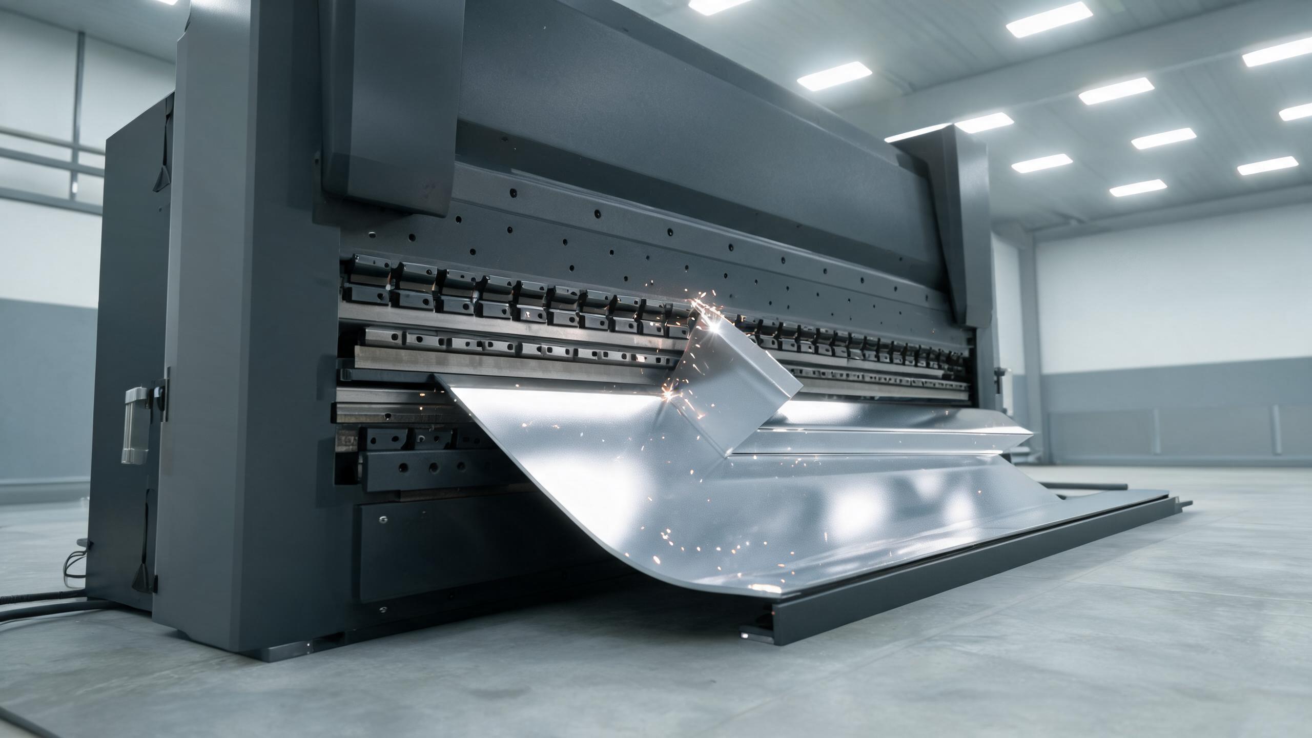
Splitting cutting and bending across two suppliers adds a second datum, re-fixturing, and tolerance stack-up. This procurement guide explains what changes when metal cutting and bending services run in one workflow: datum consistency, bend allowances planned at the cut stage, fewer handoffs, and how to evaluate a supplier against your actual part data.
Procurement Guide · Cutting & Bending
A cut blank and a bent part are usually two separate purchases. When a bracket is cut at one supplier and bent at another, the second shop inherits a part it did not dimension, and the buyer inherits the gap between those two interpretations. Buying metal cutting and bending services from one workflow removes that gap — but only if the supplier actually plans the bend at the cut stage, not just runs two machines under one roof.
What actually changes in a single workflow
- One datum. The cut profile and the bend lines are defined against the same reference, so the flat pattern already accounts for the bend allowance rather than correcting it later.
- No re-fixturing. The part is not re-clamped on a second machine with a new zero point, so positional uncertainty does not compound.
- Fewer handoffs. One drawing revision, one inspection record, one party accountable for the finished feature relationship.
- Springback and sequence planned once. Compensation and bend order are decided before the first cut, not discovered at the press brake.
Why splitting cutting and bending costs tolerance
Tolerance stack-up is not a single big error. It is several small ones that each look acceptable on their own. When a laser or punch shop cuts to a flat pattern and a separate brake shop bends it, three things are added to the part's error budget:
- Each shop establishes its own datum from the drawing. A hole pattern referenced from one edge at the cutter and from another edge at the bender rarely lines up perfectly at the finished assembly.
- The flat pattern was developed without confirmed tooling on the bending side. If the actual punch and die radius differ from the assumption, the bend allowance used at the cut stage is wrong.
- Re-fixturing introduces a second setup. Every new setup adds locating variation, and that variation is invisible until parts are measured in the assembled state.
None of this means a two-supplier route cannot work. It means the buyer is underwriting the interface between two shops, and the drawing must carry enough tolerance headroom to absorb the misalignment.
Datum consistency: the core difference
A datum is the reference from which features are located. In a single-workflow shop, the same datum can be carried from the cutting program through to the bend table and the final inspection. That lets the shop control the relationship between, for example, a hole pattern and a bend line as a designed feature, not as the sum of two independent operations.
Practically, this shows up in three places:
| Stage | Split workflow | Single workflow |
|---|---|---|
| Cut program | Flat pattern developed from an assumed bend radius | Flat pattern developed against the actual tooling planned for that part |
| Setup | Part re-clamped on a second machine with a new zero | Same reference held from cut to bend |
| Inspection | Two records, two parties, interface unchecked | One record, feature relationships measured as designed |
The table describes the general mechanism, not a claim that every single-workflow shop performs identically. Confirm the actual process against your drawing.
Bend allowance planned at the cut stage
Bend allowance is the flat-pattern length you must add or subtract so the part reaches the correct finished dimension after forming. If the cut stage does not know the bend stage's tooling, the allowance is a guess that the bender later tries to compensate for. In a single workflow, the allowance is set when the cut program is written.
The machine matters here. A TRUMPF TruMatic 6000, for example, combines laser and punch operations in one unit, so a flat pattern can combine punched features, laser-cut profiles, and forming operations defined for the same part. Whether that equipment is appropriate for your part depends on material, thickness, and feature geometry — it is not automatically the best route for every job.
Two planning steps belong at the cut stage, not after it:
- Bend sequence planning. The order in which bends are formed affects where the part is gripped and whether an earlier bend obstructs a later one. Deciding this before cutting prevents the situation where a finished cut blank cannot be formed as drawn.
- Springback compensation. Formed metal relaxes after the punch releases. Compensating for it requires knowing the material, thickness, and tooling together — inputs that are available in one workflow and often missing when the brake shop receives only a cut blank.
What the shop needs from you to plan the workflow
The workflow advantage is only realized if the supplier receives the right inputs. Provide:
- Controlled drawing revision with the datum and critical features identified.
- Material grade and thickness — for example CRS, HRS, 304 or 316 stainless, 5052 or 6061 aluminum, or galvanized sheet — since bend behavior differs between them.
- Bend angle and inside radius requirements, or a statement that the shop may select them.
- Any assembled-state or mating-part condition that defines the acceptance criterion.
Typical bending capability and its boundaries
As a general reference point for metal cutting and bending services, typical bending covers material thickness from 0.5 mm to 6 mm, with thicker sections reviewed case by case. Standard bend angles run from 0° to 90°, with up to 135° available. A common minimum inside radius is 1.0× material thickness, though this should be confirmed per drawing because it depends on tooling and material ductility.
These are starting conditions, not a promise for every part. A tight inside radius in 6 mm stainless is a different question from the same radius in 0.5 mm cold-rolled steel, and the answer should come from the shop reviewing your specific drawing.
Quality system and verification
For buyers who need to qualify a supplier, the quality system is part of the route. An IATF 16949:2016-registered quality system — held by a manufacturer founded in 2009, for example — indicates process discipline relevant to automotive and similar supply chains. A registration is a system-level credential; it describes how the facility manages quality, not a guarantee about any single part. Ask whether the shop's system scope covers your part type.
For new or complex parts, a first article inspection (FAI) is the practical verification step. The FAI measures the actual part against the drawing so that the assumed bend allowance, sequence, and springback compensation can be validated before production. Treat an approved FAI as confirmation for the parts and conditions it covers, not as proof that any future revision will perform identically.
Procurement checklist
Use these questions when comparing a single-workflow supplier against a split route:
- Will the bend allowance be planned from the actual tooling, or from a default assumption?
- Which datum will be used for the cut features and the bent features, and is it the same datum?
- Is the bend sequence defined before cutting, and who confirms it?
- Is springback compensation applied at the forming stage, and how is it verified?
- Does the inspection record measure feature relationships or only individual dimensions?
- Is an FAI available, and what does it cover?
- Can the shop flag a drawing whose tolerance cannot be held with the proposed tooling?
How this maps to the available services
If you are evaluating capability, the relevant service pages are:
- Custom laser cutting services — profile and flat-pattern cutting.
- Custom sheet metal bending services — forming to drawing, including sequence and springback handling.
- Custom sheet metal bending services — one source covering both stages.
For a deeper look at how bend allowances and springback interact with tolerance, see the related article on sheet metal bending techniques for B2B buyers: K-factor, springback, and tolerance control.
FAQ
Does one supplier for cutting and bending always reduce cost?
It reduces the number of setups and the interface risk between two shops, which are the usual sources of extra work and scrap on a split route. Whether that translates to a lower total cost depends on your part, volume, and the terms you are quoted — compare both routes against the same drawing and acceptance criteria rather than assuming one is cheaper.
Can a single-workflow shop still hold a tolerance that a split route cannot?
A single workflow removes the re-fixturing and cross-shop interpretation steps from the stack-up. That improves the achievable relationship between cut features and bent features. The actual tolerance still depends on material, thickness, tooling, and part geometry, so it must be confirmed against your drawing.
Do I still need an FAI if both operations are in one shop?
An FAI is the verification that the planned allowance, sequence, and compensation actually produce the part as drawn. It is useful in both routes, and it is the record that lets you approve a production run with confidence about the specific part and revision it covers.
Next step
Send the controlled drawing for the parts in question, noting material, thickness, bend angles, inside radii, and the assembled-state requirement. Ask the supplier to confirm the datum, bend allowance basis, springback compensation, FAI scope, and whether an IATF 16949:2016-registered quality system covers your part type. Comparing answers on those points tells you more than comparing machines alone.